Now that you’ve seen how to write and run a simple ECharts program, we’re ready to take a look a closer look at the ECharts language and what it can do. In the following sub-sections we provide a brief overview of ECharts language features.
ECharts permits nesting a machine in a machine’s state. ECharts supports two approaches to nesting machines: (1) inner machines and (2) external machines.
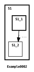
Here’s a simple example of a nested inner machine:

In this example, an inner machine is nested in the initial state S1 of the root (or top-level) machine, Example0002. Variables and methods defined in the parent machine are accessible to nested inner machines.
ECharts also supports nesting parameterized externally defined machines. This, in turn, supports machine re-use. Here’s an example:
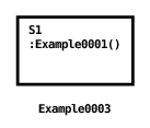
In this example, the Example0001 machine is nested in state S1 of the Example0003 machine. We discuss parameterized nested machines in Section 3.3.4. Access permissions for external machines are discussed in Section 4.9.
In the previous example, the nested machine’s identity is declared as a constant. Using ECharts reflective invocation, the nested machine can also be declared as a variable whose value is the machine’s fully qualified class name as shown in this example:
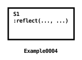
This example also shows how host language statements are wrapped in host language delimiters <* *>. When Java is the host language, variable declarations, method declarations and inner class declarations must be wrapped in host language delimiters. For more details concerning the ECharts/host language interface see Section 3.16.
There are four kinds of action that may execute during a machine’s execution: (1) a transition action, (2) an entry action, (3) an exit action, (4) a constructor.
As we’ve seen in the examples above, an ECharts machine can perform actions when its machine transitions fire.
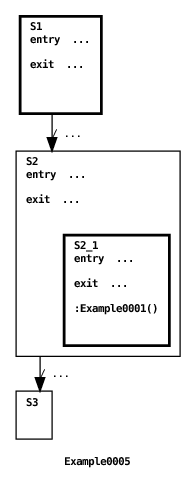
A machine can also perform actions upon entry to or exit from a machine’s state. A state’s exit action is executed when a firing transition explicitly references the state as a source state. A state’s entry action is executed when a firing transition explicitly references the state as a target state. For example:
This program produces the following output:
When the first transition fires, its source explicitly references state S1 which results in its exit action being executed. The same transition’s target explicitly references state S2 which results in its entry action being executed. When the second transition fires, its source explicitly references state S2 which results in its exit action executing. Notice that the entry action for S1 and the entry and exit actions for S2_1 are not executed because neither of these two states are explicitly referenced by transition source or target. Entry actions execute top-down as a new machine state is entered. Exit actions execute bottom-up as an old machine state is exited. More details concerning entry and exit actions are discussed in the section devoted to machine pseudostates in Section 3.10.
In the previous example, only single line action statements were used. Actions can also be grouped together into multi-line action blocks as follows:
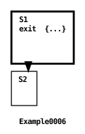
As you can see from this example, action blocks are enclosed by curly brackets { } and individual actions are delimited with a semicolon.
In this section we discuss the different types of ECharts machines and states and how they are defined.
So far, all our example machines have been instances of or-state machines. An or-state machine consists of or-states, exactly one of which is the machine’s current state at any given time. For this reason an or-state machine corresponds to the traditional notion of a state machine.
The states of an and-state machine are and-states. Unlike an or-state machine, all states of an and-state machine are current states. As such, and-state machines support concurrent machine operation. Here’s an example:
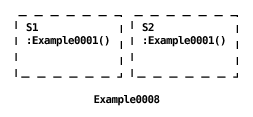
This machine concurrently runs two instances of the Example0001 machine. And-states are graphically depicted with dashed lines. Here’s the machine’s output:
The machine declaration includes the concurrent machine modifier, marking it as an and-state machine. Inner submachines may also be declared as concurrent. Since both of the machine’s states are current states there is no need to declare a state with the initial state modifier.
As its name implies, a mixed-state machine contains both or-states and and-states. In fact, or-state machines and and-state machines are just special cases of mixed-state machines. Here’s an example of a mixed-state machine.
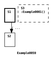
And here’s one of two possible machine outputs:
As shown in the example, individual and-states in a mixed state machine, like state S3, are declared as concurrent (and or-states aren’t). In the example, the top-level machine transitions from the initial or-state S1 to or-state S2, thereby changing the current or-state from S1 to S2. However, the and-state S3 is always current, regardless of the current or-state. State S3 nests the simple “Hello World!” machine discussed in Section 2.1. Because S3 is an and-state, its submachine can execute concurrently with the transition occurring between the or-states S1 and S2. This is why the machine has two possible outputs depending on which transition fires first.
In light of this discussion you will recognize that an or-state machine is just a mixed-state machine consisting only of or-states, and an and-state machine is a mixed-state machine consisting only of and-states. It follows that the concurrent machine modifier, used to declare a machine as an and-state machine, is just a short-hand for declaring all the states of the machine to be concurrent. Like or-state machines and and-state machines, mixed-state machines can be used as internal or external submachines.
For more insight into how concurrently executing states operate see Section 4.3. Also, in Section 4.8 we discuss data sharing amongst concurrent submachines. In Sections 4.5.1 and 4.8 we discuss in detail how transitions are chosen to fire across concurrent submachines.
ECharts machines may declare multiple constructors if desired. By default, all machines implicitly declare a zero-argument constructor. This has been the case for all the examples to this point. The next example shows how to declare a machine constructor and how to invoke the constructor from another machine.
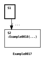

The Example0017 machine invokes the Example0018 machine when it transitions from S1 to S2. When the transition fires the transition action initializes the value of the Example0018 machine constructor parameter. The parameter value is referenced by the Example0018 machine constructor when its own transition fires, resulting in the following output:
This section describes the different forms that state transitions may take.
In the previous examples, transitions have referenced states in the same machines the transitions are declared in. ECharts also supports transitions referencing states declared in submachines, as shown in this example:
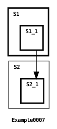
Here, the transition source references state S1_1 of the submachine nested in S1, and the transition target references state S2_1 of the submachine nested in state S2.
Machine state access permissions can be specified to dictate whether a state can be referenced by a transition. See Section 4.9 for further discussion.
When mixed-state or and-state machines are used, the programmer may want a transition to reference more than one concurrent state. To do this ECharts supports the concept of fork and join transitions. Here’s an example:
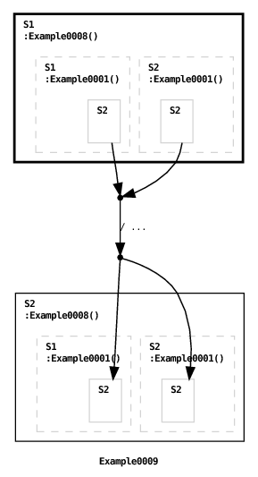
The graphical syntax depicts fork and join points with small filled circles. States of external submachines that are explicitly referenced by a machine’s transitions are graphically depicted with gray borders. If an external machine’s states aren’t explicitly referenced then they are not shown in order to reduce clutter.
Here’s the machine’s output:
The source states referenced by the (join) transition in the root machine Example0009 are sub-states of the and-state machine Example0008 nested in S1. Similarly the target states referenced by the (fork) transition are sub-states of the and-state machine Example0008 nested in S2.
The previous example illustrated the use of fork/join transitions in a top-level or-state machine. Here’s an example using them for a top-level and-state machine.
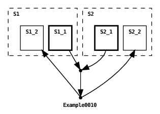
We discuss mixed-state and and-state machine transitions further in Section 3.15.
A predicate, called a guard, can be specified for a transition. In order for a transition to fire it is necessary for the transition’s guard to evaluate to true. For example:
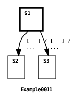
Because i is initialized to 0, only the first transition will be enabled so this machine will transition to state S2.
Guards can also be grouped into if-elif-else style compound statements as shown in the following example:
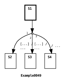
The graphical syntax depicts branching points as small hollow circles and branch segments include branch numbers to indicate guard evaluation order. And here’s the output from the example:
In this example there is a single transition with three possible targets. The resulting target depends on which of the three guards evaluates to true. The guards are evaluated in the order they are written just as they are in other languages such as Java. This permits minimizing the number of calls to expensive operations that may be invoked when evaluating guards. In the example, the first guard condition is the only one that invokes the expensiveOperation() method. This guard has the side-effect of initializing the value of the result variable to the result returned by the method. Subsequent guard conditions reference the result value instead of re-invoking the method. Note that in this example we wrap host language method and variable declarations in host language delimiters. For more details concerning the ECharts/host language interface see Section 3.16.
Here’s an example showing how compound targets can be nested.
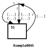
And here’s the output from the example:
In this example, there is a single transition with nested compound targets. The machine iterates two times from state S1 to state S1, each time printing out the iteration number.
We discuss guards further in Section 3.5.
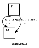
All the transitions in the examples discussed so far have been messageless transitions. We now introduce message transitions. An ECharts machine reacts to its environment when it receives messages on ports specified by its message transitions. ECharts defines two classes of ports to receive messages on: external ports and internal ports. External ports support interaction with the environment outside a machine (see Section 3.9), and internal ports support interaction within a machine (see Section 3.14). In this section we discuss receiving messages from the external environment. Consider the following example machine:
Here’s the machine’s environment:
First, the machine’s environment creates an instance of the machine and runs it on a separate thread. The MachineThread class is a convenience class that does nothing more than call the machine’s run() method. The machine’s thread blocks waiting for a message to arrive on p1. Then the machine’s environment puts a message, a String instance, in external port p1’s input queue. The arrival of the message unblocks the machine’s thread, and the transition specifying a String message fires, printing out the message. ECharts also supports non-blocking machine execution, described in Section 3.6.
A message transition uses the port receive syntax p1 ? Classname to specify waiting on external port p1 for a message that is an instance of the Classname class. When the transition’s guard is evaluated and when the transition’s action is executed, the message instance is made available as a distinguished variable named message. The port instance is made available as a distinguished variable named port. While this variable’s value is redundant here, it is useful for ‘*’ transitions (see Section 3.7).
When enabled message transitions specify the same port and same received message, then the ECharts runtime will give highest priority to the transition specifying the most specific message class. Here’s an example:
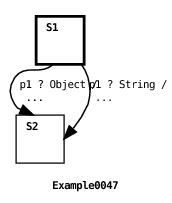
This example shows the machine’s run() method invoked directly by the environment’s main() method as an alternative to creating a separate MachineThread instance as shown in the previous example. When the machine is executed the runtime chooses the second transition to fire because it specifies the String class which is more specific than the Object class (which is a superclass of the String class). This transition priority rule is the first of three transition priority rules supported by the ECharts runtime. These rules are discussed in more detail in Section 4.5.
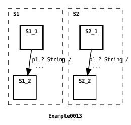
A given external port can be referenced by more than one transition in a machine, for example, by transitions in different concurrent submachines of an and-state machine:
Here’s the previous machine’s environment:
In this example, the machine’s environment puts two messages in p1’s input queue. The two transitions in the machine’s concurrent states fire in succession producing one of two possible outputs. Here’s one possible output:
Normally, a port variable’s value will remain constant throughout the life of a machine. However, if a port’s value is expected to change then there are constraints on how that value may be changed. This is discussed in more detail in Section 4.8.2.
We discuss the blocking machine execution cycle in more detail in Section 4.1. A non-blocking alternative is discussed in the next section, Section 3.6. We discuss how messages received from the environment are dequeued in more detail in Section 4.6.
In the last two examples we discussed how the thread that invokes a machine’s run() method can block while awaiting the arrival of messages specified by message transitions in the machine’s current state. ECharts also provides a non-blocking run() method that can be useful in some application domains such as HTTP or SIP servlet containers. Here’s how the machine in the previous example would be executed using a non-blocking approach:
Here, the machine’s environment creates a machine instance (where Machine0014 is identical to Machine0013) and then invokes the non-blocking run() method two times. The arguments for the run() method specify the port p1 and the message associated with the port.
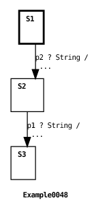
In the case where the non-blocking run() method is invoked specifying port p and no active message transitions specify p in the machine’s current state then the message will be enqueued on p’s input queue in accordance with the implicit message deferral model supported by the ECharts runtime (see Section 4.6.2). Messages enqueued as a result of earlier run() invocations may be dequeued and processed by later run() invocations in accordance with the runtime’s explicit message consumption model (see Section 4.6.1). Here’s an example:
And here’s the example’s output:
In this example, the environment invokes the machine’s non-blocking run() method two times: first with a message for port p1 and then with a message for port p2. Since the only message transition specifying p1 is not active in the machine’s initial state S1, then p1’s message is enqueued on p1’s input queue and the machine’s state remains unchanged the first time run() is invoked. When run() is invoked a second time, the message transition specifying p2 fires. Then the method dequeues p1’s message and fires p1’s transition because the transition is active in state S2.
A blocking approach to machine execution is discussed in the previous section, Section 3.5.
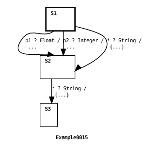
A variation on the message transition is the ‘*’ (“any port”) transition. The ‘*’ transition is a message transition that specifies a wildcard port. In particular, it matches any port that is explicitly mentioned in some other message transition in a machine’s current state. Here’s an example machine using a ‘*’ transition:
And here’s the machine’s environment:
Here’s the machine’s output:
In this example, the machine’s environment puts two String instances in external port p1’s input queue. The only transition to explicitly reference p1 in state S1 specifies a Float message. However, the ‘*’ transition in S1 does specify a String instance and, since the ‘*’ matches any port specified by a transition in the current state, it matches p1 and fires. Notice that the ‘*’ transition action references a distinguished variable named port whose value is the matched port. In state S2, port p1 has one String message remaining in its input queue. Furthermore, there is a ‘*’ transition defined in that state. However, since there are no transitions explicitly referencing p1 in S2 the ‘*’ transition is not enabled to fire. For more information regarding message queuing see Section 4.6.
Naturally, in addition to receiving messages, a machine can also send messages to its environment or to ancestor/descendant machines via external or internal ports, respectively. Here’s an example:
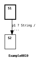
In this example, the environment creates two external ports and sets them as each other’s peers using the setPeer() method. Setting a port’s peer means that when a message is sent on a port, the message will be placed in the peer port’s input queue. (In Section 3.9 we discuss another way for the environment to receive messages from a machine.) Next, two instances of the Example0019 machine are created and run on separate threads. Each machine’s constructor is invoked with different values for its port and message. Executing the machine constructor sends the specified message on the specified port which enqueues the message on the peer port’s input queue. The syntax for a message send operation is port ! message. Since port input queue size is unbounded the port send operation is non-blocking. The port send operation can be used anywhere actions are permitted i.e. in state entry/exit actions, transition actions, or machine constructors. Finally, each machine waits for a message to arrive on its own input queue. When the message arrives, its transition fires and the message is printed. One possible output from this example is:
We discuss how messages received from the environment are dequeued in more detail in Section 4.6.
As we have seen in the previous examples, an external port maintains a input queue of messages that it has received but has not yet processed. To send messages on a port, the programmer must configure the port to output the messages to a particular destination.
Example0019 showed that in order to enqueue messages sent out on a port, the port can be peered with another port. However, queuing output messages is not always necessary. Instead, it may be desirable to simply invoke a listener method in the environment when a machine outputs a message. This can be accomplished by overriding the external port’s output() method as shown in the next example:
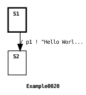
In this example the machine’s environment creates an instance of an (anonymous) ExternalPort subclass. The subclass specifies that the output() method should simply print any message sent on that port, which is precisely what happens when the Example0020 machine fires its transition.
Messages may also be sent to remote external port instances. For example, imagine that the two Example0020 machine instances in the previous example are running on different machines. The ExternalPort class supports this via its getRemote() method. This method returns a remote reference to the port. When a message is input to the remote port reference, either directly by calling the port’s input() method, or indirectly by invoking a message send operation ! on the port’s peer, the message is placed in the actual port’s input queue. For the Java runtime system this is accomplished via Java’s RMI.
A small number of pseudostates are defined for all machines. Unlike a real state, a pseudostate represents a machine property. Pseudostates can be included in a transition’s source or target state references.
The DEFAULT_INITIAL pseudostate references a machine’s declared initial state. This pseudostate can only be referred to as part of a transition’s target state reference. If the machine is an or-state or mixed-state machine that has not declared an initial state, then referencing its DEFAULT_INITIAL pseudostate results in a translator error.
A reference to a machine’s DEFAULT_INITIAL pseudostate is treated as an explicit reference to the machine’s initial state. Therefore, as discussed in Section 3.2.2, if an entry action is defined for the initial state then it will be executed. Here’s a simple or-state machine example using the DEFAULT_INITIAL pseudostate:
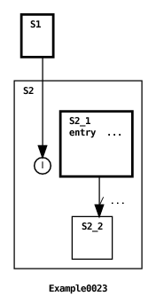
When the parent transition fires it references the DEFAULT_INITIAL pseudostate of the submachine defined in state S2. This pseudostate is graphically depicted by the letter ‘I’ enclosed by a circle. Since this is treated as an explicit reference to the submachine’s initial state, the entry action defined for the initial or-state S2_1 is executed followed by the firing of the submachine’s transition. The resulting output is:
A DEFAULT_INITIAL pseudostate reference to a machine array references the default initial states of all machine array elements. This is consistent with the rules for transition target state references discussed in Section 3.11.
If a machine possesses and-states, then referencing the machine’s DEFAULT_INITIAL pseudostate is a short-hand for referencing the initial or-states of the and-state’s submachines. While the interplay between the DEFAULT_INITIAL pseudostate and entry actions is straightforward for or-state machines, it is more subtle for mixed-state and and-state machines. If the DEFAULT_INITIAL pseudostate of a mixed-state or and-state machine is referenced, then entry actions defined for the machine’s initial or-state and and-states will be executed, however, entry actions defined for the initial states of the and-states’ submachines will not be executed. This is shown in the following example with a mixed-state machine:
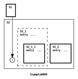
One of two possible outputs from this example is:
The transition target references the DEFAULT_INITIAL pseudostate of state S2’s submachine. When the transition fires, the entry actions for the submachine’s and-state S2_1 and initial or-state S2_2 execute. Since these two states are entered concurrently, the order their entry actions execute is nondeterministic so it is possible for the machine output to be reversed from that shown above. However, the entry action for the initial state of the submachine nested in state S2_1 is not executed because it not explicitly referenced by the DEFAULT_INITIAL pseudostate.
The TERMINAL pseudostate can only be referred to as part of a transition’s source state reference. A TERMINAL source state reference is satisfied if the referenced machine is in a terminal state. An or-state machine is defined to be in a terminal state if the machine’s current or-state is a state with no submachines and no outbound transitions. An and-state machine is in a terminal state if all of its and-state submachines are in terminal states. A mixed-state machine is in a terminal state if its current or-state is terminal and the submachines of all its and-states are in terminal states.
If a TERMINAL pseudostate references a machine array, then the reference is satisfied if at least one of the machine array elements is in a terminal state. This is consistent with the rules for transition source state references discussed in Section 3.11. Similar to what was discussed for the DEFAULT_INITIAL pseudostate in Section 3.10.1, a TERMINAL pseudostate reference is considered to be an explicit reference to a machine’s terminal state. Therefore, any exit actions defined for a terminal state referenced with the TERMINAL pseudostate will be executed. Here’s a simple example:
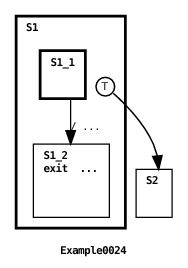
The terminal pseudostate is graphically depicted by the letter ‘T’ enclosed by a circle. The first thing to occur is the transition in state S1’s submachine fires. This results in the submachine entering a terminal or-state S1_2. This condition satisfies the source state reference of the parent machine’s transition S1.TERMINAL causing the parent to transition to state S2. Since the reference to the TERMINAL pseudostate is treated as an explicit reference to S1_2, then S1_2’s exit action is executed when the parent transition fires. Here’s the machine’s output:
Here’s another example that demonstrates the use of the TERMINAL pseudostate with a mixed-state machine.
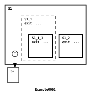
One possible machine output is:
The first thing to notice is that the state S1 submachine is initially in a terminal state. This is because its initial or-state S1_2 is a terminal state and its and-state S1_1 is in a terminal state because its submachine is in a terminal state S1_1_1. This means that the TERMINAL pseudostate reference in the transition is satisfied and the transition fires. The next thing to notice is that the TERMINAL pseudostate reference is interpreted to be an explicit reference to the two terminal states: S1_1 and S1_2. For this reason, the states’ exit actions execute but since the two states are concurrent their exit action execution order is nondeterministic. This means another possible machine output has the opposite ordering of what is shown above. The last thing to note is that the exit action for state S_1_1 is not executed because the TERMINAL pseudostate reference is not interpreted to explicitly reference this state.
We discuss how the notion of a terminal state is related to machine destruction in Section 4.7. See Section 4.5.2 for a discussion of the relative specificity of a TERMINAL pseudostate reference in the context of the source state coverage transition priority rule.
The DEEP_HISTORY pseudostate can only be referred to as part of a transition’s target state reference. DEEP_HISTORY references a machine’s current state and the current states of any of its submachines. Unlike references to the DEFAULT_INITIAL pseudostate, or the TERMINAL pseudostate discussed in Sections 3.10.1 and 3.10.2, respectively, a reference to a machine’s DEEP_HISTORY pseudostate is not considered to be an explicit reference to the machine’s current state. Therefore, any entry actions defined for the machine’s current state will not be executed when referenced via the machine’s DEEP_HISTORY pseudostate. Here’s an example that should clarify this:
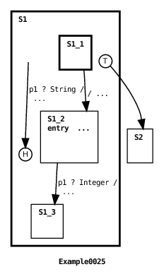
The deep history pseudostate is graphically depicted by the letter ‘H’ surrounded by a circle. In this example, the machine’s environment creates an external port p1 and then enqueues two messages on the port’s input queue: a string instance followed by an integer instance. Then the environment creates and runs the machine. The submachine defined in state S1 fires its first transition from state S1_1 to state S1_2, executing the entry action defined for S1_2, and then blocks in state S1_2 waiting for an Integer instance to arrive on p1. Then the parent’s first transition fires in response to the arrival of a String instance arriving on p1 (see Section 6.4 for an explanation of the graphical depiction of this transition). The transition’s target is the DEEP_HISTORY pseudostate of the S1 submachine. Since the submachine was in state S1_2 prior to the parent transition firing, then the submachine will return to state S1_2. Furthermore, since the DEEP_HISTORY reference does not constitute an explicit state reference, then the entry action defined for S1_2 will not be executed again. Since the next message in p1’s input queue is an Integer instance, the submachine transition from S1_2 to S1_3 will fire. Finally, since S1_3 is a terminal state, the parent’s second transition will fire. For the record, here’s the resulting output:
The DEEP_HISTORY pseudostate will be discussed further when we discuss timed transitions in Section 3.12.
The NEW pseudostate is normally used in association with machine arrays discussed in Section 3.11. When used to reference a machine array the effect is to create a new submachine element while leaving the state of any pre-existing machine elements undisturbed. In effect, a NEW pseudostate reference behaves exactly the same as a DEEP_HISTORY pseudostate reference for the pre-existing machine elements. Similarly, the NEW pseudostate behaves exactly the same as a DEEP_HISTORY pseudostate reference for and-state, or-state and mixed-state machines.
Here’s a summary of how the pseudostates are interpreted by the ECharts runtime system.
| Pseudostate | Source/Target | Implicit/Explicit |
| DEFAULT_INITIAL | target | explicit |
| TERMINAL | source | explicit |
| DEEP_HISTORY | target | implicit |
| NEW | target | implicit |
In addition to and-state submachines, ECharts supports another kind of concurrent submachine known as the machine array. A machine array is a bounded array of concurrent submachines (elements) nested within an and-state or an or-state. Unlike an and-state submachine, which is created when its parent machine is created, machine array elements must explicitly be created, one-by-one, by an ancestor machine at run-time.
Here’s an example of machine array element creation:
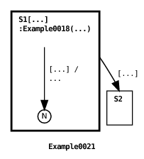
In this example, state S1 declares a machine array of size bound = 2: one element for each string element in the messages array. Machine array instances in S1 are declared to be Example0018 machines. When the Example0021 machine is initially created it is important to realize that no Example0018 instances are created. A machine instance is created only when the transition from S1 to S1.NEW fires (see Section 6.4 for an explanation of the graphical depiction of this transition). The NEW pseudostate, introduced in Section 3.10, is graphically depicted by the letter ‘N’ surrounded by a circle. When then NEW pseudostate is referred to in the context of a machine array, the effect is to create a new machine instance in the machine array. The states of any other pre-existing machine instances in the array are unaffected. After the Example0021 machine creates both Example0018 submachines, it transitions to S2. The resulting output is:
When more than one machine instance exists in a machine array, you may wonder which machine is referenced when a transition references the array. There are two simple rules: (1) a transition source state reference is satisfied if any machine in the array satisfies the source state; (2) a target state reference refers to all pre-existing machines in the array. These rules are highlighted in the following example:
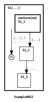
Like Example0021, this machine first creates two submachines in the machine array declared for state S1 (see Section 6.4 for an explanation of the graphical depiction of this transition), however, in this case the submachine is defined as an inner machine instead of an external machine. Once created, each submachine instance is prevented from transitioning from its initial state S1_1. (The reason for including the nonterminal state modifier for S1_1 will become clear when we discuss machine destruction in Section 4.7.) Once both submachine instances are created the source state S1.S1_1 referenced by the parent machine’s second transition is satisfied (see Section 6.4 for an explanation of the graphical depiction of this transition). This is because there exists at least one submachine in state S1_1. In fact, both submachines happen to be in this state. When the transition fires, it updates the state of both submachine instances to S1_2 enabling the submachines’ second transition to fire. The getMachineIndex() method referenced in the transition’s action returns the index of the submachine in the parent machine’s machine array. So, when the submachine transitions fire, they print out the submachines’ respective messages, one possible output being:
In general, when a machine array is referenced by a (source) join transition (see Section 3.4.2) then the interpretation is that the individual source state references may be satisfied by different machine array elements. Explicit machine references should be used in order to constrain more than one source state reference to refer to the same machine array element as explained in Section 3.11.2.5.
Section 3.11.1 explains how transitions can implicitly reference machine array elements. In this section we describe how transitions can also explicitly reference particular machine array elements. This is accomplished using indexed machine array references. There are two forms of indexed reference: as a settor to obtain a particular array element index, or as a gettor to specify a particular array element index. Index settors and gettors are described in Sections 3.11.2.1 and 3.11.2.3, respectively.
Our first example shows the use of a settor to obtain the indices of created and destroyed machine array elements.
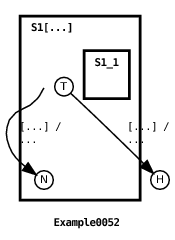
The output from this machine is:
In Example0052, the parent machine initially creates 3 machine array elements (see Section 6.4 for an explanation of the graphical depiction of this transition). A target index settor, expressed with the notation S1[?i].NEW is used to obtain the index value of an array element when it is created. The settor assigns the index value of the newly created element to the parent’s i variable. The value obtained is then output by the state S1 entry action.
Target index settors are only applicable to machine array element creation i.e. they are only applicable to NEW target state references. A target index settor assignment occurs after the execution of the associated transition’s actions, but before the execution of state entry actions that may execute as a result of the transition firing. This means that the value assigned by a target index settor is not available to the associated transition’s action, but it is available for reference by state entry actions. Furthermore, the value assigned to a variable by a settor persists after the associated transition fires unless, of course, the variable is explicitly assigned a new value by some other machine action or settor.
Example0052 also illustrates the use of source index settors. In this example, the source index settor is expressed with the notation S1[?i].TERMINAL. This settor obtains the index value of an array element when it is in a terminal state. When the associated transition fires, the settor assigns the index value of the referenced element to the parent’s i variable. The value obtained is then output by the transition’s action.
Source index settors are applicable to any transition source state reference, not simply TERMINAL pseudostate references. A source index settor assignment occurs before any state exit actions execute and before the associated transition’s guard or action executes. This means that the value assigned by a source index settor is available for reference by state exit actions, and it is available for reference by the associated transition’s guard and action.
But now a word of caution with regards to the persistence of the value assigned by a source index settor: a side-effect of evaluating possible values for a source index settor is that the variable referenced by the settor may be overwritten during the evaluation process. For this reason, if one wants the value obtained by a source index settor to persist after its associated transition has fired then the value should be re-assigned to a variable that is not referenced by a source index settor as part of the associated transition’s action.
Another constraint is that each variable referenced in a source index settor should be unique for a given transition i.e. a variable shouldn’t be shared across a transition’s source index settors.
The use of settor-initialized variables in transition guards is discussed in more detail in Section 3.11.2.2. Other examples of source index settors are given in Sections 3.11.2.4, and 3.11.2.5, 4.8.
As mentioned in Section 3.11.2.1, an index assigned by a source index settor can be referenced in the associated transition’s guard. In this case the ECharts runtime searches for an index value that both satisfies the transition’s source state reference and the transition’s guard. If such an index is found then the transition will be a candidate for firing. Here’s an example:
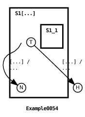
Here’s the machine’s output:
In this example, the parent machine first creates 4 machine array elements (see Section 6.4 for an explanation of the graphical depiction of this transition). Then the machine’s second transition fires twice: only for array elements that are in their terminal states and whose index value modulo 2 is equal to 0.
Whereas Section 3.11.2.1 shows how to obtain an array element index to be utilized by the ECharts runtime, this section deals with how to specify an array element index utilized by the ECharts runtime. The following machine provides examples of both source and target index gettors.
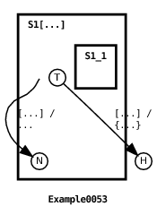
The machine’s output is:
Unlike the machine in Example0052, the machine in this example specifies the index for each newly created array element. The target index gettor S1[i].NEW informs the ECharts runtime to use the value assigned to the machine’s variable i as the index of the newly created array element (see Section 6.4 for an explanation of the graphical depiction of this transition). Similarly, the source index gettor S1[j].TERMINAL declares that the transition source state reference should be satisfied only when the array element whose index is specified by variable i is in a terminal state.
A precaution one must take when utilizing index gettors is to ensure that the specified array element actually exists. This means that the programmer must keep track of which array elements are free and which aren’t. Like most arrays, the value of a machine array index ranges from 0 to 1 minus the array’s specified bound. A free element becomes occupied when an array element is created (via a NEW pseudostate reference). An occupied element becomes free when the array element is destroyed. For details regarding machine creation and destruction see Section 4.7.
Index settors and gettors may be used to reference nested machine array elements as shown in the following example:
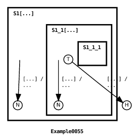
The output from this machine is:
In this example the parent machine creates two machine array elements in state S1, and each of these elements creates two elements of their own in state S1.S1_1 (see Section 6.4 for an explanation of the graphical depiction of this transition). The second parent transition specifies a source index gettor S1[1] and a source index settor S1_1[?i]. As a result, the second parent transition fires twice: once when S1[1].S1_1[0] reaches its terminal state, and once when S1[1].S1_1[1] reaches its terminal state.
Index settors and gettors may be used to simultaneously reference peer machine array elements as shown in the following example:
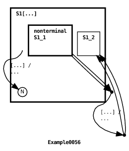
One possible output from this machine is:
In the example, the parent machine creates four machine array elements in S1 (see Section 6.4 for an explanation of the graphical depiction of this transition). The second parent transition specifies two source index settors S1[?i].S1_1 and S1[?j].S1_1. The transition guard further constrains i != j. This means that the source state is satisfied when two distinct peer array elements are found to be in state S1_1 (The reason for including the nonterminal state modifier for S1_1 will become clear when we discuss machine destruction in Section 4.7.). The transition’s target state reference specifies two target index gettors S1[i].S1_2 and S1[j].S1_2. This means that if the transition fires with source index settor values i = 0 and j = 1, then peer array elements S1[0] and S1[1] will both transition to state S1_2.
This example also shows that, in general, individual source state references may be satisfied by different machine array elements. In order to constrain source state references to refer to the same array element use the approach shown in the following example:
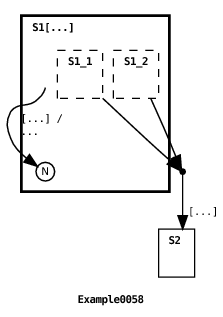
See Section 6.4 for an explanation of the graphical depiction of the first transitions in this machine.
In Section 4.5.1 we discuss how message transitions are chosen to fire across machine array elements. In Section 4.8.1, we discuss how messageless transitions are chosen to fire across machine array elements. In Section 3.13 we discuss how an ancestor machine can access data and methods in machine array elements. In Section 4.8 we discuss data sharing amongst machine array elements.
Timed transitions are used for triggering timed events. A timed transition’s timer is activated (starts ticking if it wasn’t already ticking) when the state referenced by the transition’s source becomes the current state. Here’s a simple example:
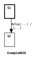
All this machine does is pause in state S1 for 1000 ms prior to transitioning to state S2. The transition’s action prints out the values of three distinguished variables available during timed transition actions: duration, activationTime, and expiryTime. duration is the duration in ms associated with the transition, activationTime is the timestamp in ms at which the transition’s timer became activated, and expiryTime is the timestamp in ms at which the transition’s timer expired. Note that the expiry time is not necessarily equal to the time that the transition fires since other transitions may fire in the interval between the transition timer’s expiry and the transition firing. For further discussion concerning the relative priority of ports and transitions, see Sections 4.4 and 4.5.
Beyond being simply activated, a timed transition’s timer will be reactivated (activated with its counter reset) if the state referenced by the transition’s source is explicitly referenced by the previously firing transition’s target. On the other hand, a timed transition’s timer will remain activated or expired if referenced with a DEEP_HISTORY pseudostate (the DEEP_HISTORY pseudostate is discussed in more detail in Section 3.10.3). Here’s an example of both of these concepts:
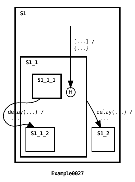
In this example, the initial state of the machine activates the timers for the two timed transitions. Both timers are activated with the same duration value of 1000 ms. However, the first transition to fire is the messageless transition which changes the duration value. Because the transition’s target state explicitly references state S1.S1_1, the timer for the (shallow) transition whose source state is S1.S1_1 is reactivated with the new duration value (see Section 6.4 for an explanation of the graphical depiction of this transition). But the timer for the (deep) transition whose source state is S1.S1_1.S1_1_1 remains activated with the original duration value because it is referenced with a DEEP_HISTORY pseudostate. Here’s the machine’s output:
A timed transition whose duration is 0 ms will immediately be enabled. A timed transition whose duration has a negative value will never be enabled.
When a guard condition is specified for a timed transition, it is important that the guard’s true and false conditions be handled by the transition itself using compound targets (see Section 3.4.3). This is because if the transition’s timer expires and no target is defined for the transition then an exception will be raised. See Section 4.6.1 for a detailed explanation of this behavior. The interested reader is referred to [1] for a formal description of the rules used to determine timed transition activation and reactivation.
Submachine fields and methods can be accessed from transition guards, transition actions, and entry/exit actions. Every machine maintains variables for referencing its submachines. A submachine’s variable name is the same as its state’s name. Here’s an example:
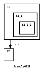
In this example, the root machine accesses the fields named field in submachines defined for states S1 and S1.S1_1. The machine’s output is:
Here’s another example, this time illustrating machine array element access (see Section 3.11).
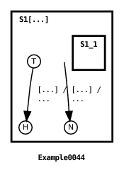
Here’s the machine’s output:
In this example, two machine array elements are initially created. The machine array elements consist only of a single state that plays the role of both the machine’s initial state and its terminal state (see Section 3.10.2). Following their creation (see Section 6.4 for an explanation of the graphical depiction of this transition), the second transition is enabled to fire for each element. As described in Section 3.11.2.1, the notation S1[ ?index ].TERMINAL has the effect of setting the index variable to the value of the machine array element index satisfying the transition’s source state reference. The resulting index value is used to access the message field of the referenced machine array element in the transition’s action.
We discuss precisely when submachine variable values are set and cleared in Section 4.7. Submachine variable access is constrained by machine and state access permissions. This topic is discussed in Section 4.9. Also, there are constraints on shared data referenced by transitions. This is discussed in Section 4.8.
Internal ports are intended to make communications between ancestor and descendant machines explicit. An internal port is nothing more than a first-in-first-out queue. Like external ports, messages can be sent and received on internal ports. Unlike external ports, an internal port does not need to be peered in order to support sending messages. Whenever possible, internal ports should be used in lieu of shared data (discussed in Section 4.8). The following example shows how internal ports are used.
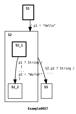
The example machine output is:
In the example, internal port p1 is created by the parent machine and internal port p2 is created by the submachine in state S2. A machine that creates an internal port is considered to “own” the port.
Messages are sent and received on internal ports using the same syntax used to send and receive messages on external ports (see Section 3.9). In the example, the parent machine first sends the message "Hello" on p1 which is received on p1 by the submachine. The submachine then sends the message "World!" on p2 which is received on p2 by the parent machine. The priority of an internal port is between that of a timed transition port and an external port. See Section 4.4 for more details.
A machine transition’s source and target state references need not specify a state at all. When no source state is referenced then the transition’s source state is satisfied regardless of the current state of the machine. When no target state is referenced then the target state is treated as a reference to the machine’s DEEP_HISTORY pseudostate (see Section 3.10.3). Here’s an example:
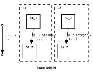
In this example, the machine’s environment enqueues two messages in external port p1’s input queue. This port is then passed to the machine as a constructor parameter. The machine maintains two concurrent submachines. One increments messages when a String instance arrives on p1 and the other increments messages when an Integer instance arrives on p1 (see Section 6.4 for an explanation of the graphical depiction of these transitions). When the number of messages to arrive on p1 reaches two, the transition with no specified source or target state fires. Since this transition specifies no target state, the target is treated as a DEEP_HISTORY reference. As shown in the machine diagram, the graphical notation for an empty source or target state reference is a small empty box.
When we introduced join and fork transitions in Section 3.4.2 the examples showed all of a machine’s and-states being explicitly referenced. This is not necessary in general. Omitting an and-state or or-state reference in a transition’s source is treated as a “don’t care” reference. Omitting an and-state or or-state reference in the transition’s target is treated as a DEEP_HISTORY reference. These points are illustrated in the following example:
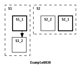
In this example, the transition explicitly references and-state S1 but not and-state S2 (see Section 6.4 for an explanation of the graphical depiction of this transition). Since state S2 is not referenced in the transition’s source state, then S2 is guaranteed to satisfy the transition’s source state. Furthermore since S2 is not referenced in the transition’s target state, then the reference to S2 is treated as a DEEP_HISTORY pseudostate. When the transition executes, state S1 changes from S1_1 to S1_2 and state S2 remains in S2_1.
In Section 1 we introduced ECharts as a hosted language. This means that ECharts was never intended to be a complete programming language. Rather, ECharts relies on an underlying host language to support data operations and low-level control flow. ECharts strives to make the boundary between itself and its host language as seamless as possible while also trying to be independent from its host language. Experience gathered from earlier versions of ECharts has led us to adopt a boundary where basic language expressions are directly supported by the ECharts language, but more complex host control-flow constructs and field and method declarations are contained within host language delimiters. Consistent with ECharts adoption of other Java concepts, ECharts has adopted Java-style expressions. These expressions are translated appropriately to the chosen target host language. Escaped host constructs delimited by <* *>, are stripped of their delimiters and inserted directly into the translated code.
It is easiest to describe which ECharts expressions are acceptable indirectly by enumerating those Java expressions that are not acceptable ECharts expressions and, therefore, must be wrapped in host language delimiters: instanceof, if, then, else, try, catch, throw, switch, case, do, while, for, synchronized, return, continue, break, assert, ?: ternary operator, method declarations, variable declarations, and inner class declarations.
In the ECharts grammar a host language element wrapped in <* *> plays the role of a primary expression. As such it may be embedded in a larger ECharts expression. For example, a transition guard for a Java hosted machine might look like this:
ECharts machines and associated classes are serializable to support their use in a high-availability environment. Serializability makes it possible to store and retrieve ECharts objects to and from a replicated data tier. Here’s an example using the Javamachine runtime to save and restore a machine and a port to and from a file:
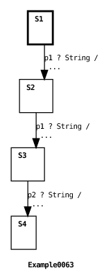
The example machine simply waits for a message to arrive on port p1 in states S1 and S2, then it waits for a message to arrive on port p2. When the machine is executed with the Example0063Environment, the environment first runs the machine using non-blocking execution (see Section 3.6) providing a message for port p1. This causes the machine to transition from state S1 to S2. Then the environment runs the machine providing a message for port p2 but because no transitions in state S2 reference p2, then the message is enqueued on the p2’s input queue and the machine remains in state S2. Finally, the environment serializes and writes port p1 and the machine to the file Example0063.tmp. The output that results from running Example0063Environment is:
Next Example0064Environment is executed which reads and deserializes port p1 and the machine from the file Example0063.temp. Then the environment runs the machine with a message for port p1. This first causes the machine to transition to state S3. Then, because there is a message enqueued for port p2 and there is a transition defined for p2 in state S3, the machine transitions to state S4. The output that results is:
See Section 5.4 for information on serialized machines with delay transitions.